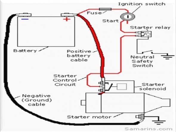
When it comes to the starting system of a vehicle, the starter motor plays a crucial role in getting the engine running. A wiring diagram for the starter motor is essential for understanding how the various components are connected and how they work together to start the engine.
With the help of a wiring diagram, you can easily identify the different wires, terminals, and components of the starter motor system. This knowledge can be useful for troubleshooting any issues that may arise with the starter motor, such as failure to start or unusual noises during startup.
Wiring Diagram Starter Motor
The wiring diagram of a starter motor typically includes the battery, ignition switch, starter solenoid, starter relay, and the starter itself. The battery provides the power needed to start the engine, while the ignition switch activates the starter system.
The starter solenoid is responsible for engaging the starter motor when the ignition key is turned. The starter relay acts as a switch that controls the flow of power to the starter motor, while the starter itself is the component that physically turns the engine over to start it.
Each component in the starter motor system is connected by specific wires that are color-coded for easy identification. By referring to the wiring diagram, you can trace the path of each wire and ensure that all connections are secure and functioning properly.
It is important to follow the wiring diagram carefully when working on the starter motor system to avoid causing damage to the components or risking injury. If you are unsure about any aspect of the wiring diagram, it is best to consult a professional mechanic or electrician for assistance.
In conclusion, a wiring diagram for the starter motor is a valuable tool for understanding the electrical connections and components of the starting system. By familiarizing yourself with the diagram, you can effectively troubleshoot and maintain the starter motor to ensure smooth and reliable engine starts.
