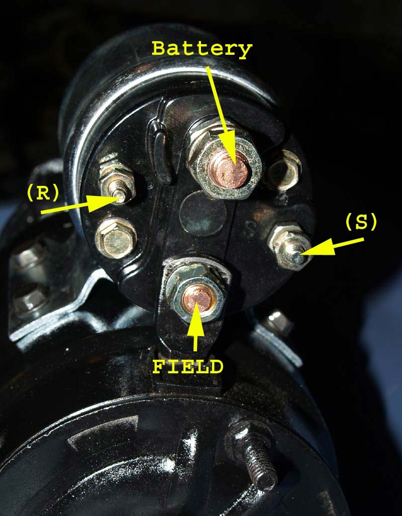
When it comes to starting a vehicle, the starter motor solenoid plays a crucial role in the process. This small yet powerful component is responsible for engaging the starter motor and turning the engine over. Understanding how the wiring diagram for the starter motor solenoid works is essential for proper installation and troubleshooting.
Before diving into the wiring diagram, it’s important to have a basic understanding of how the starter motor solenoid functions. When the ignition key is turned, an electrical signal is sent to the solenoid, which then engages the starter motor. This action allows the starter motor to crank the engine and start the vehicle.
 Wiring Diagram For Starter Motor Solenoid
Looking at the wiring diagram for the starter motor solenoid, you will typically see four terminals labeled “S,” “M,” “B,” and “C.” The “S” terminal is connected to the ignition switch, the “M” terminal is connected to the starter motor, the “B” terminal is connected to the battery, and the “C” terminal is connected to the chassis ground.
It’s important to ensure that the wiring connections are secure and free of corrosion to prevent any starting issues. If you are experiencing problems with your starter motor solenoid, referring to the wiring diagram can help identify any potential issues with the wiring or connections.
When installing a new starter motor solenoid, always refer to the manufacturer’s instructions and wiring diagram to ensure proper installation. Incorrect wiring can lead to malfunctioning of the starter system, causing starting issues and potential damage to other components.
In conclusion, understanding the wiring diagram for the starter motor solenoid is essential for proper installation and troubleshooting. By following the proper wiring connections and referring to the diagram, you can ensure that your vehicle starts smoothly and reliably. Always consult a professional if you are unsure about any wiring connections or if you are experiencing starting issues.