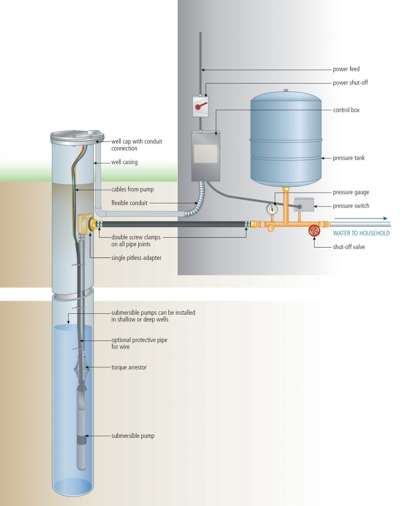
Well pump wiring diagrams are essential for understanding how to properly wire your well pump system. Whether you are installing a new well pump or troubleshooting an existing one, having a wiring diagram can help you navigate the complex wiring connections.
Proper wiring is crucial for the safe and efficient operation of your well pump. It ensures that power is distributed correctly to all components, preventing damage or malfunction. With a well pump wiring diagram, you can easily identify the different wires and terminals, making it easier to troubleshoot any issues that may arise.
Components of a Well Pump Wiring Diagram
A typical well pump wiring diagram includes components such as the pump motor, pressure switch, control box, and power supply. The diagram shows how these components are connected through wires and terminals, guiding you on how to make the proper connections.
It is important to follow the wiring diagram provided by the manufacturer to ensure that your well pump operates safely and efficiently. Incorrect wiring can lead to overheating, short circuits, or even electrical fires. By referring to the wiring diagram, you can avoid these potential hazards and ensure that your well pump system functions as intended.
When working with well pump wiring, always remember to turn off the power supply before making any connections. Use proper tools and equipment, and follow all safety precautions to prevent accidents. If you are unsure about any aspect of the wiring process, consult a professional electrician for assistance.
In conclusion, a well pump wiring diagram is a valuable tool for installing, troubleshooting, and maintaining your well pump system. By understanding the components and connections outlined in the diagram, you can ensure that your well pump operates safely and efficiently. Remember to always follow the manufacturer’s instructions and prioritize safety when working with electrical systems.
