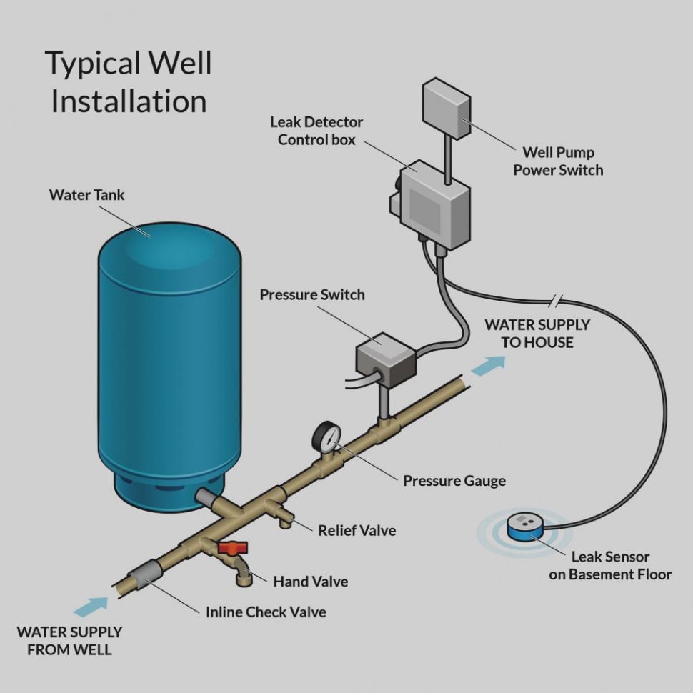
When it comes to installing a well pump pressure switch, it is important to understand the wiring diagram to ensure proper installation and operation of the pump. The pressure switch is responsible for turning the pump on and off based on the water pressure in the system. Understanding how to wire the pressure switch is essential for the pump to function correctly.
Before starting the installation process, it is crucial to familiarize yourself with the wiring diagram provided by the manufacturer. The diagram will show you how to connect the different wires from the pressure switch to the pump and power source. It is important to follow the diagram carefully to prevent any issues with the pump’s operation.
 Well Pump Pressure Switch Wiring Diagram
Typically, the pressure switch will have four terminals labeled as Line In, Line Out, Load In, and Load Out. The Line In terminal is where the power source is connected, while the Line Out terminal is connected to the pump. The Load In terminal is where the power source is connected again, and the Load Out terminal is connected to the pump. Following the wiring diagram, you will connect the wires accordingly to these terminals.
It is important to ensure that all connections are secure and properly insulated to prevent any electrical hazards. Once the wiring is complete, you can test the pump by turning on the power and monitoring the water pressure. If the pump turns on and off at the correct pressure levels, then the installation was successful.
In conclusion, understanding the wiring diagram for a well pump pressure switch is essential for proper installation and operation of the pump. By following the diagram provided by the manufacturer and making sure all connections are secure, you can ensure that your well pump functions correctly. If you are unsure about the wiring process, it is always best to consult a professional to avoid any potential issues.