USB (Universal Serial Bus) is a common interface used for connecting various devices to a computer. Understanding the wiring schematic diagram of USB can help in troubleshooting connectivity issues and building custom USB cables.
In this article, we will delve into the details of USB wiring schematic diagram and discuss its components and connections.
USB Wiring Schematic Diagram
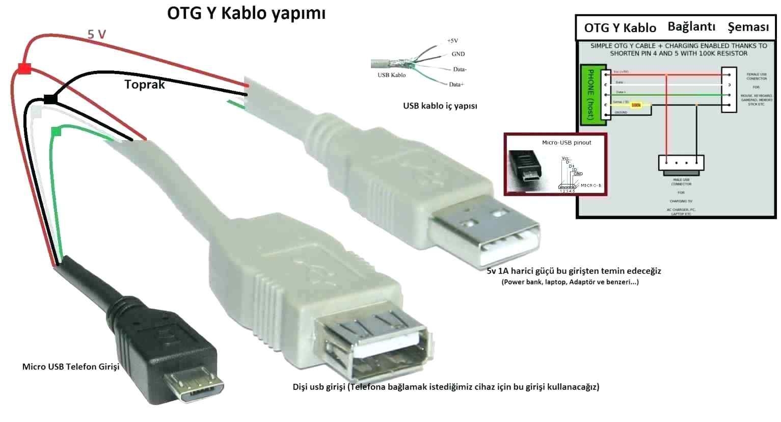
A USB cable consists of four wires – VCC, GND, D+, and D-. VCC is the power line, GND is the ground line, D+ is the data line for transmitting data from the device to the host, and D- is the data line for transmitting data from the host to the device.
The wiring schematic diagram of USB follows a standard color coding scheme – red for VCC, black for GND, green for D+, and white for D-. It is important to follow this color coding while making custom USB cables to ensure proper connectivity.
When building a USB cable, it is crucial to understand the pinouts of the USB connector. The USB connector has four pins – 1 for VCC, 2 for D-, 3 for D+, and 4 for GND. By correctly connecting the wires to these pins, you can ensure the proper functioning of the USB cable.
Additionally, it is essential to pay attention to the orientation of the USB connector while soldering the wires. The USB connector has a specific orientation, and reversing the connections can lead to connectivity issues. Refer to the wiring schematic diagram to ensure the correct orientation of the USB connector.
In conclusion, understanding the USB wiring schematic diagram is essential for building custom USB cables and troubleshooting connectivity issues. By following the standard color coding scheme and pinouts of the USB connector, you can ensure proper connectivity and data transmission between devices and computers.
