USB ports are commonly used for connecting various devices to a computer or other electronic devices. Understanding the wiring diagram of a USB port can be helpful in troubleshooting connectivity issues or for DIY projects involving USB connections.
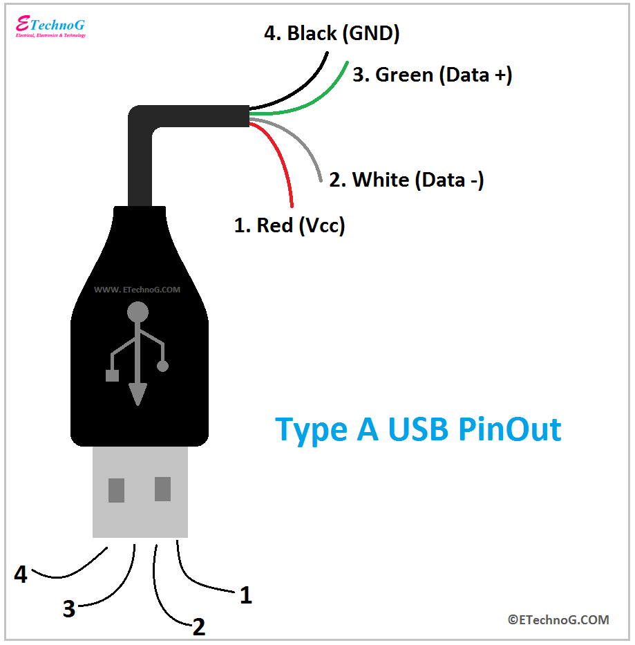
A USB port wiring diagram typically shows the pin assignments for the different wires inside the USB cable. This includes the power, ground, data, and sometimes additional pins for specific functions like OTG (On-The-Go) or charging. By following the wiring diagram, you can ensure that the USB connection is properly set up.
USB Port Wiring Diagram
There are several types of USB connectors, including Type-A, Type-B, Mini USB, Micro USB, and USB-C. Each type of connector has a specific pinout configuration that corresponds to the wiring diagram. For example, a USB Type-A connector has four pins – VBUS (power), D- (data -), D+ (data +), and GND (ground).
When connecting a USB device, it is important to match the pins on the device with the corresponding pins on the USB port. Incorrect wiring can result in malfunction or damage to the device. It is also crucial to ensure that the wires are properly insulated and secured to prevent short circuits.
For DIY projects involving USB connections, having a clear understanding of the wiring diagram can help in customizing USB cables or creating adapters for specific purposes. By following the correct pin assignments, you can create reliable and functional USB connections for your projects.
In conclusion, understanding the wiring diagram of a USB port is essential for ensuring proper connectivity and functionality of USB devices. Whether you are troubleshooting issues or working on DIY projects, having knowledge of the pinout configuration can be beneficial. By following the guidelines provided in the wiring diagram, you can create secure and efficient USB connections.
