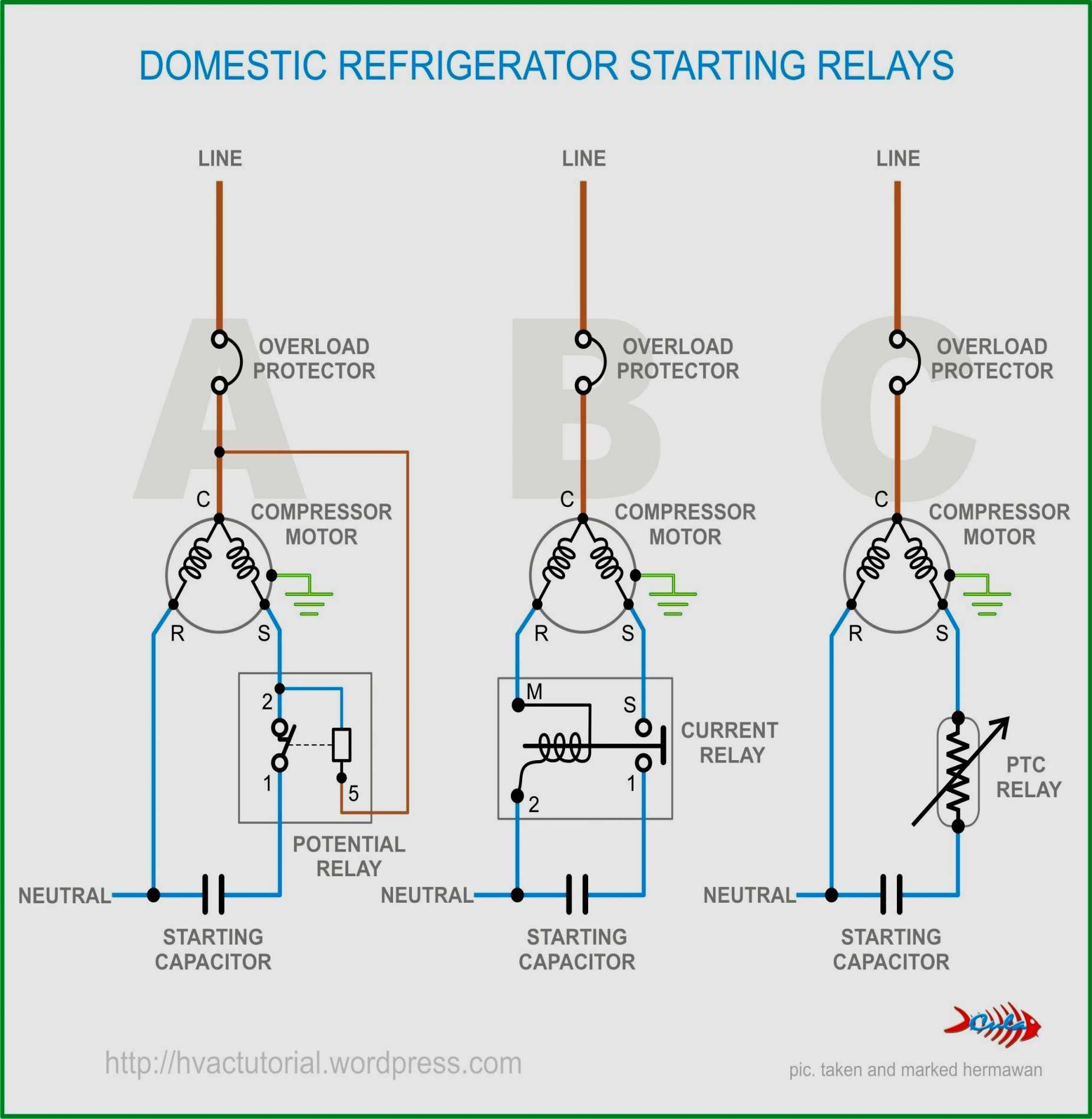
Three phase motors are commonly used in industrial applications due to their efficiency and power. Understanding how to wire a three phase motor is essential for proper installation and operation. In this article, we will discuss the basics of three phase motor wiring diagram.
Before wiring a three phase motor, it is important to identify the type of motor you have – whether it is a delta or wye connection. The wiring diagram will vary depending on the type of connection, so make sure to consult the motor’s manual or manufacturer for the correct wiring instructions.
 Three Phase Motor Wiring Diagram
Wiring Connections
Three phase motors have three windings – labeled as A, B, and C. Each winding is connected to a different phase of the power supply. The most common wiring configuration for a three phase motor is the delta connection, where each winding is connected in series to form a closed loop. The wye connection, on the other hand, connects one end of each winding together to create a neutral point.
When wiring a three phase motor in a delta configuration, the A phase is connected to B phase, B phase to C phase, and C phase to A phase. For a wye connection, the A, B, and C phases are connected to their respective terminals, with the neutral point connected to the center point of the windings.
It is important to follow the wiring diagram provided by the motor manufacturer to ensure proper installation and prevent any damage to the motor. Make sure to double-check the connections before powering up the motor to avoid any electrical hazards.
In conclusion, wiring a three phase motor requires careful attention to detail and following the correct wiring diagram. Understanding the type of connection and how to properly wire the motor will ensure smooth operation and prevent any issues down the line. Always consult the motor’s manual or manufacturer for specific instructions on wiring your three phase motor.