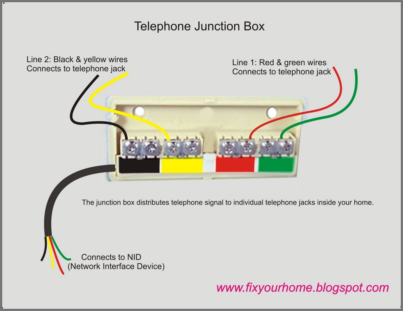
Telephone line wiring diagrams are essential for understanding how to properly install and troubleshoot telephone lines in homes and businesses. These diagrams provide a visual representation of the wiring connections that need to be made in order for the telephone system to function correctly.
Whether you are setting up a new telephone line or repairing an existing one, having access to a wiring diagram can help you identify any issues and ensure that the connections are made correctly.
Components of a Telephone Line Wiring Diagram
A typical telephone line wiring diagram will include the following components:
- Telephone jack
- Telephone line cord
- Telephone wall plate
- Telephone network interface device (NID)
- Telephone wires (usually color-coded)
By following the wiring diagram and connecting these components in the correct order, you can ensure that your telephone line is properly installed and functioning correctly.
It is important to note that telephone line wiring diagrams may vary depending on the type of telephone system being used. For example, a landline telephone system will have different wiring requirements than a VoIP system. Be sure to consult the specific wiring diagram for your telephone system to ensure proper installation.
If you encounter any issues with your telephone line, such as static on the line or dropped calls, refer to the wiring diagram to troubleshoot the problem. By following the wiring connections and checking for any loose or damaged wires, you can identify and resolve the issue quickly.
In conclusion, telephone line wiring diagrams are valuable tools for installing and troubleshooting telephone lines. By understanding the components and connections outlined in the diagram, you can ensure that your telephone system operates efficiently and effectively.
