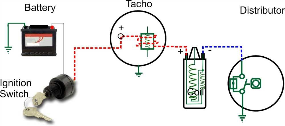
Whether you are a car enthusiast or a professional mechanic, having a tachometer installed in your vehicle is essential for monitoring engine speed. However, simply installing a tachometer is not enough – proper wiring is crucial to ensure accurate readings and prevent damage to your vehicle.
Improper wiring can lead to inaccurate readings and potential damage to the tachometer or other components of your vehicle. To avoid these issues, it is important to follow a wiring diagram specific to your tachometer model and vehicle make and model.
Tachometer Wiring Diagram
When wiring a tachometer, it is important to connect the correct wires to ensure proper functionality. Typically, a tachometer will have four wires: power, ground, signal, and illumination. The power wire should be connected to a switched 12V power source, the ground wire to a suitable ground point, the signal wire to the ignition coil or tachometer output terminal, and the illumination wire to the dashboard lighting circuit.
It is important to refer to the wiring diagram provided with your tachometer to ensure proper connections. Additionally, using the correct gauge of wire and proper connectors will help prevent any issues with the tachometer’s performance.
Once the tachometer is properly wired, it is important to test the functionality before securing the wiring in place. Start the vehicle and verify that the tachometer is displaying accurate readings. If there are any issues, double-check the wiring connections and consult the wiring diagram for troubleshooting tips.
Properly wiring a tachometer is essential for accurate engine speed monitoring and overall vehicle performance. By following the wiring diagram specific to your tachometer model and vehicle make and model, you can ensure that your tachometer functions correctly without any issues.
In conclusion, proper wiring of a tachometer is crucial for accurate readings and overall vehicle performance. By following the wiring diagram provided with your tachometer and double-checking the connections, you can ensure that your tachometer functions correctly and provides you with valuable engine speed information.
