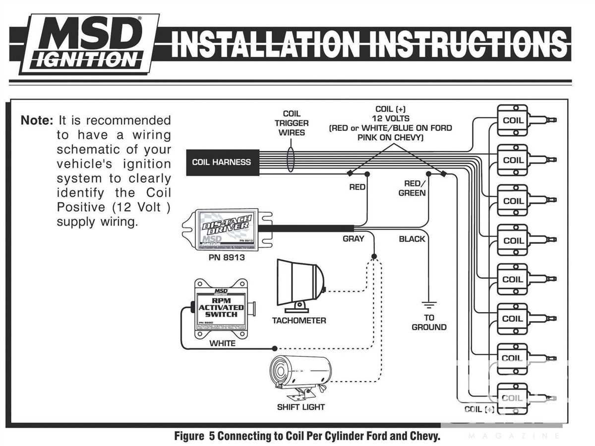
When it comes to installing a tachometer in your vehicle, having a proper wiring diagram is essential. A tachometer, or ‘tach’ for short, is a crucial tool for monitoring the RPM (revolutions per minute) of your engine. This information is vital for keeping your engine running smoothly and efficiently. Without a proper wiring diagram, you may run into issues with installation and accuracy of the tachometer readings.
A tach wiring diagram provides a visual representation of how to properly wire your tachometer to your vehicle’s engine. It typically includes detailed instructions on where to connect the tachometer’s wires to the ignition system, coil, and other components. Following the wiring diagram ensures that your tachometer will function correctly and provide accurate RPM readings.
One of the most common mistakes when installing a tachometer is incorrect wiring. Without a proper wiring diagram, it can be easy to connect the tachometer wires to the wrong components, leading to inaccurate readings or even damage to the tachometer itself. By following a tach wiring diagram, you can avoid these issues and ensure that your tachometer works as intended.
Additionally, a tach wiring diagram can also help troubleshoot any issues that may arise with your tachometer. If you notice that your tachometer is not displaying accurate readings or is not working at all, referring to the wiring diagram can help identify potential problems with the wiring connections. This can save you time and frustration when trying to diagnose and fix any issues with your tachometer.
Overall, a tach wiring diagram is an invaluable tool for anyone looking to install or troubleshoot a tachometer in their vehicle. By following the wiring diagram, you can ensure that your tachometer is properly connected and functioning correctly. Whether you’re a seasoned mechanic or a DIY enthusiast, having a tach wiring diagram on hand is essential for a successful tachometer installation.
Don’t overlook the importance of a tach wiring diagram when installing a tachometer in your vehicle. By following the provided instructions, you can ensure that your tachometer works accurately and reliably, providing you with valuable information about your engine’s performance.
