When it comes to setting up a network, one of the most important components is the RJ45 connector. This small but crucial piece of equipment is used to connect Ethernet cables to various devices such as computers, routers, and switches. Understanding the wiring diagram for the RJ45 connector is essential in ensuring proper connectivity and data transmission.
The RJ45 connector wiring diagram is a standardized way of arranging the wires within the connector for proper signal transmission. By following this diagram, you can ensure that your network connections are secure and reliable.
Rj45 Connector Wiring Diagram
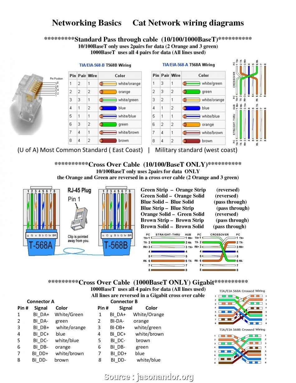
The RJ45 connector has eight pins, with each pin corresponding to a specific color-coded wire. The wiring diagram for the RJ45 connector is as follows:
Pin 1 (White/Orange)
Pin 2 (Orange)
Pin 3 (White/Green)
Pin 4 (Blue)
Pin 5 (White/Blue)
Pin 6 (Green)
Pin 7 (White/Brown)
Pin 8 (Brown)
Each wire must be carefully inserted into the correct pin slot to ensure proper connectivity. It is essential to follow the wiring diagram precisely to avoid any issues with signal transmission.
Once the wires are inserted into the correct pins, the RJ45 connector can be crimped to secure the connection. It is crucial to double-check the wiring before crimping to avoid any mistakes that could lead to network connectivity issues.
By following the RJ45 connector wiring diagram, you can easily set up reliable network connections for your home or office. Proper wiring ensures that data is transmitted efficiently and securely between devices, allowing for smooth communication and file sharing.
In conclusion, understanding the RJ45 connector wiring diagram is essential for setting up a reliable network connection. By following the standardized wiring diagram and ensuring proper wire placement, you can create secure and efficient network connections for all your devices.
