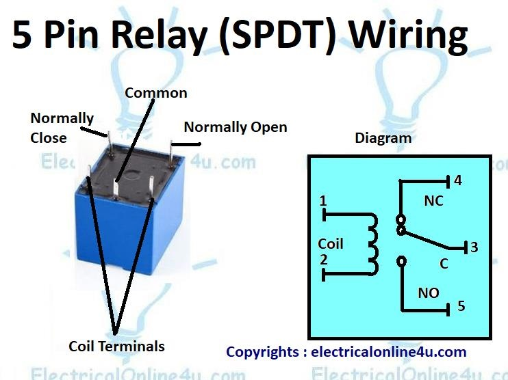
Relays are essential components in electrical systems, acting as switches that control the flow of electricity. Understanding how to wire a relay properly is crucial for ensuring the safe and efficient operation of various devices and systems. One common type of relay wiring diagram is the 5-pin relay, which is widely used in automotive applications and other industries.
A 5-pin relay consists of five terminals: two for the coil and three for the switch contacts. The terminals are typically labeled as 30, 85, 86, 87, and 87a. Terminal 30 is the common connection for the power supply, while terminals 87 and 87a are the normally open and normally closed contacts, respectively. Terminals 85 and 86 are for the coil, which creates the magnetic field that activates the switch contacts.
When wiring a 5-pin relay, it is important to follow the correct wiring diagram to ensure proper functionality. Terminal 30 should be connected to the power source, while terminals 87 and 87a are connected to the load. Terminals 85 and 86 are connected to the control switch or device that triggers the relay. It is also crucial to use the appropriate wire gauge and connectors to prevent overheating and ensure a reliable connection.
One common application of a 5-pin relay is in automotive lighting systems, where the relay is used to control the high beams or auxiliary lights. By using a relay, the load on the control switch is reduced, preventing overheating and prolonging the switch’s lifespan. Additionally, relays can be used to control various other electrical devices, such as motors, fans, and solenoids, in a wide range of applications.
Overall, understanding how to wire a relay properly is essential for ensuring the safe and efficient operation of electrical systems. The 5-pin relay wiring diagram provides a clear guide on how to connect the terminals correctly to achieve the desired functionality. By following the wiring diagram and using the right components, users can ensure reliable performance and prevent potential damage to the relay and connected devices.
In conclusion, the relay wiring diagram 5 pin is a valuable resource for anyone looking to wire a relay for their electrical system. By understanding the terminal connections and following the correct wiring procedure, users can ensure the proper operation of the relay and connected devices. Proper wiring not only ensures safety but also maximizes the efficiency and longevity of the electrical system.
