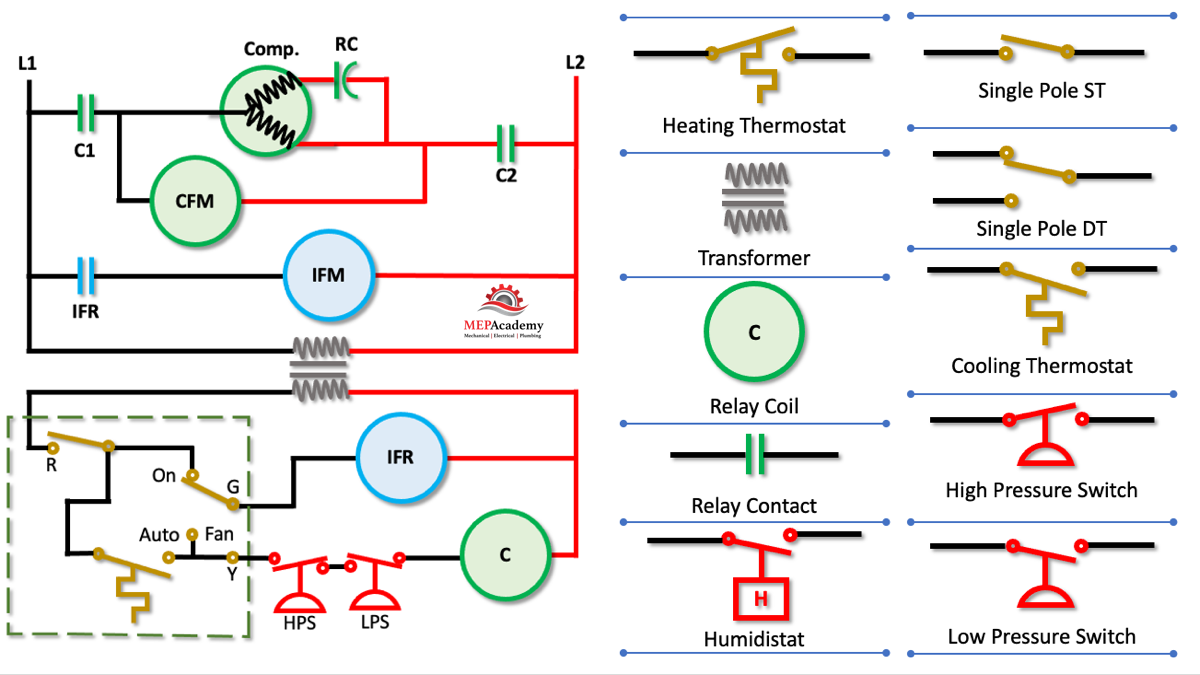
Heating, ventilation, and air conditioning (HVAC) systems are crucial for maintaining a comfortable indoor environment. These systems rely on complex wiring diagrams to ensure proper functioning. Understanding these diagrams is essential for HVAC technicians and homeowners alike.
An HVAC wiring diagram is a detailed schematic that illustrates the connections between various components in an HVAC system. These diagrams show the placement of wires, terminals, and other electrical components, allowing technicians to troubleshoot issues and make repairs effectively.
One key component of an HVAC wiring diagram is the thermostat, which controls the temperature settings in the system. The thermostat is connected to the HVAC unit through a series of wires, each serving a specific function. Understanding the color-coding of these wires is crucial for proper installation and maintenance.
Another important aspect of HVAC wiring diagrams is the control board, which acts as the brain of the system. The control board receives signals from the thermostat and other sensors, directing the operation of the HVAC unit. By following the wiring diagram, technicians can identify and address any issues with the control board.
In addition to the thermostat and control board, HVAC wiring diagrams also include details about the compressor, fan motor, and other key components. These diagrams provide a roadmap for technicians to follow when troubleshooting electrical problems or installing new equipment.
In conclusion, HVAC wiring diagrams are essential tools for understanding the complex electrical systems that power heating, ventilation, and air conditioning units. By familiarizing yourself with these diagrams, you can ensure that your HVAC system operates efficiently and effectively. Whether you are a homeowner or a technician, having a solid grasp of HVAC wiring diagrams is key to maintaining indoor comfort.
