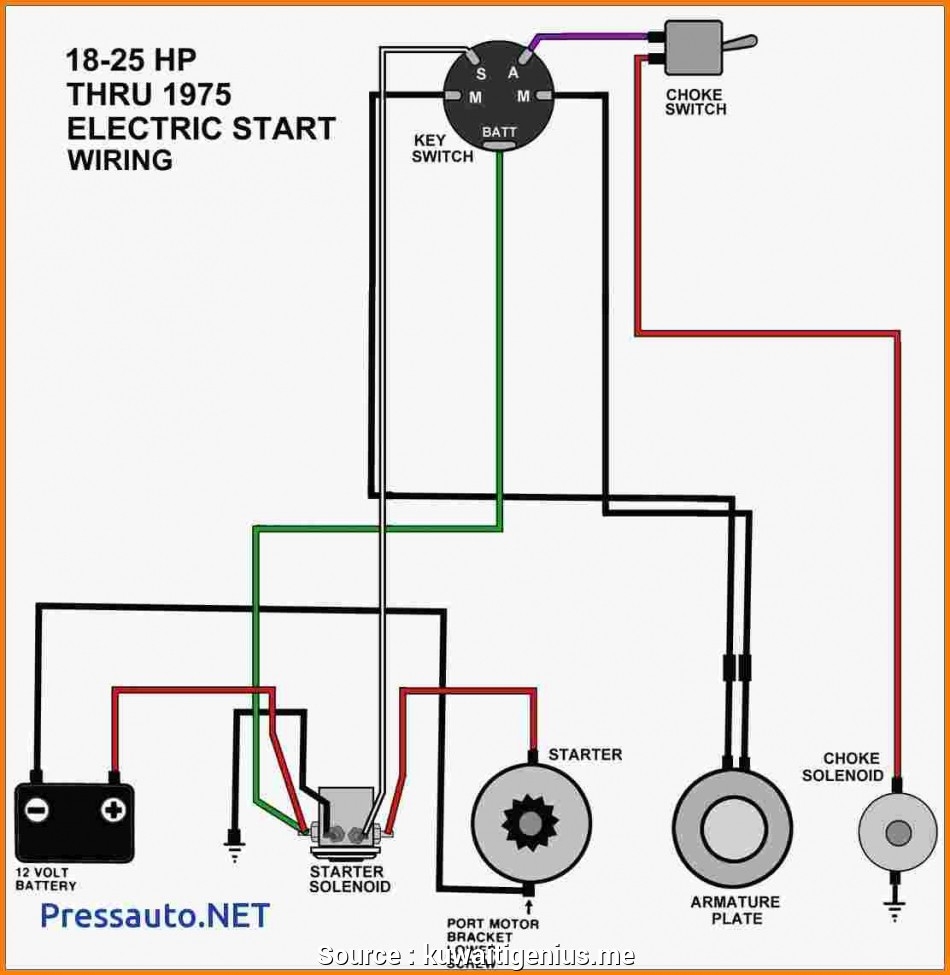
When it comes to troubleshooting the starting system on your Ford vehicle, understanding the wiring diagram for the starter solenoid is essential. The starter solenoid is a key component that helps to engage the starter motor and start the engine. By following the wiring diagram, you can easily identify any issues with the wiring and make necessary repairs.
It is important to note that the wiring diagram for the Ford starter solenoid may vary depending on the model and year of your vehicle. It is always recommended to refer to the specific wiring diagram for your vehicle to ensure accuracy.
 Ford Starter Solenoid Wiring Diagram
Ford Starter Solenoid Wiring Diagram:
1. The first step in understanding the wiring diagram is to identify the terminals on the solenoid. Typically, there are four terminals on the solenoid – two large terminals for the battery and starter motor, and two smaller terminals for the ignition switch and ground.
2. The large terminal on the solenoid that is connected to the battery should have a thick wire attached to it, usually a red wire. This wire provides power to the solenoid when the ignition switch is turned to the start position.
3. The other large terminal on the solenoid is connected to the starter motor and should have a thick wire attached to it as well, typically a black wire. This wire carries power from the solenoid to the starter motor to engage it and start the engine.
4. The smaller terminals on the solenoid are for the ignition switch and ground. The terminal connected to the ignition switch should have a thinner wire attached to it, usually a yellow wire. This wire carries power from the ignition switch to the solenoid to activate it when the key is turned to the start position.
5. The last terminal on the solenoid is for the ground and should have a wire attached to it that is connected to the vehicle’s chassis. This wire provides a ground connection for the solenoid to complete the circuit.
By understanding the Ford starter solenoid wiring diagram and following the steps outlined above, you can easily troubleshoot any issues with the starting system on your vehicle and make necessary repairs. Remember to always refer to the specific wiring diagram for your vehicle to ensure accuracy.