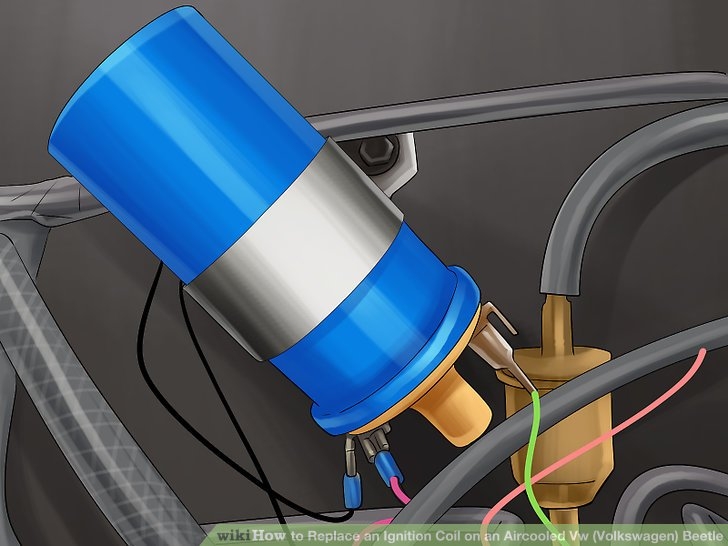
When it comes to the ignition system of a vehicle, the engine coil plays a crucial role in converting the low voltage from the battery into the high voltage needed to ignite the fuel mixture in the engine cylinders. Understanding the wiring diagram of the engine coil is essential for proper troubleshooting and maintenance of the ignition system.
The engine coil wiring diagram typically consists of a primary winding, a secondary winding, and a high voltage terminal. The primary winding is connected to the battery through the ignition switch, while the secondary winding is connected to the spark plugs. The high voltage terminal is where the high voltage output is sent to the distributor or directly to the spark plugs.
It is important to follow the correct wiring diagram when installing or replacing the engine coil in a vehicle. The primary winding should be connected to the positive terminal of the battery and the ignition switch, while the secondary winding should be connected to the spark plugs. Any incorrect connections can result in poor ignition performance or even damage to the engine coil.
Some engine coils also have additional components such as a capacitor or a resistor for improved performance and reliability. These components are usually connected in parallel with the primary winding to help reduce radio frequency interference and improve spark quality. It is important to consult the wiring diagram provided by the manufacturer to ensure proper installation of these components.
In conclusion, understanding the engine coil wiring diagram is essential for proper maintenance and troubleshooting of the ignition system in a vehicle. By following the correct connections and ensuring that all components are properly installed, you can ensure reliable ignition performance and prevent potential damage to the engine coil. Always refer to the manufacturer’s instructions and wiring diagram when working on the ignition system of your vehicle.
