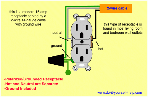
Electrical outlet wiring diagrams are essential for understanding how to properly install and wire electrical outlets in your home or building. These diagrams provide a visual representation of the electrical circuit and connections needed to power outlets safely and efficiently.
Whether you are a DIY enthusiast or a professional electrician, having a clear understanding of electrical outlet wiring diagrams is crucial for ensuring the safety and functionality of the electrical system in your home. By following these diagrams, you can avoid potential hazards and ensure that your outlets are wired correctly.
 Electrical Outlet Wiring Diagram
When wiring electrical outlets, it is important to follow the National Electrical Code (NEC) guidelines and local building codes to ensure compliance and safety. The wiring diagram will show you the proper wire connections, grounding requirements, and any additional components needed for each outlet.
Typically, electrical outlet wiring diagrams will include information on how to wire outlets in series or parallel, how to connect multiple outlets on the same circuit, and how to wire GFCI (Ground Fault Circuit Interrupter) outlets for added safety. These diagrams may also include information on how to wire outlets with different voltage requirements.
It is important to remember that working with electricity can be dangerous, and if you are not confident in your abilities to properly wire electrical outlets, it is always best to consult a professional electrician. By following the wiring diagram and taking the necessary safety precautions, you can ensure that your electrical outlets are installed correctly and safely.
In conclusion, electrical outlet wiring diagrams are an essential tool for anyone working with electrical systems. By understanding how to read and follow these diagrams, you can ensure that your outlets are wired correctly and safely. Remember to always follow the NEC guidelines and local building codes when working with electricity to avoid any potential hazards.