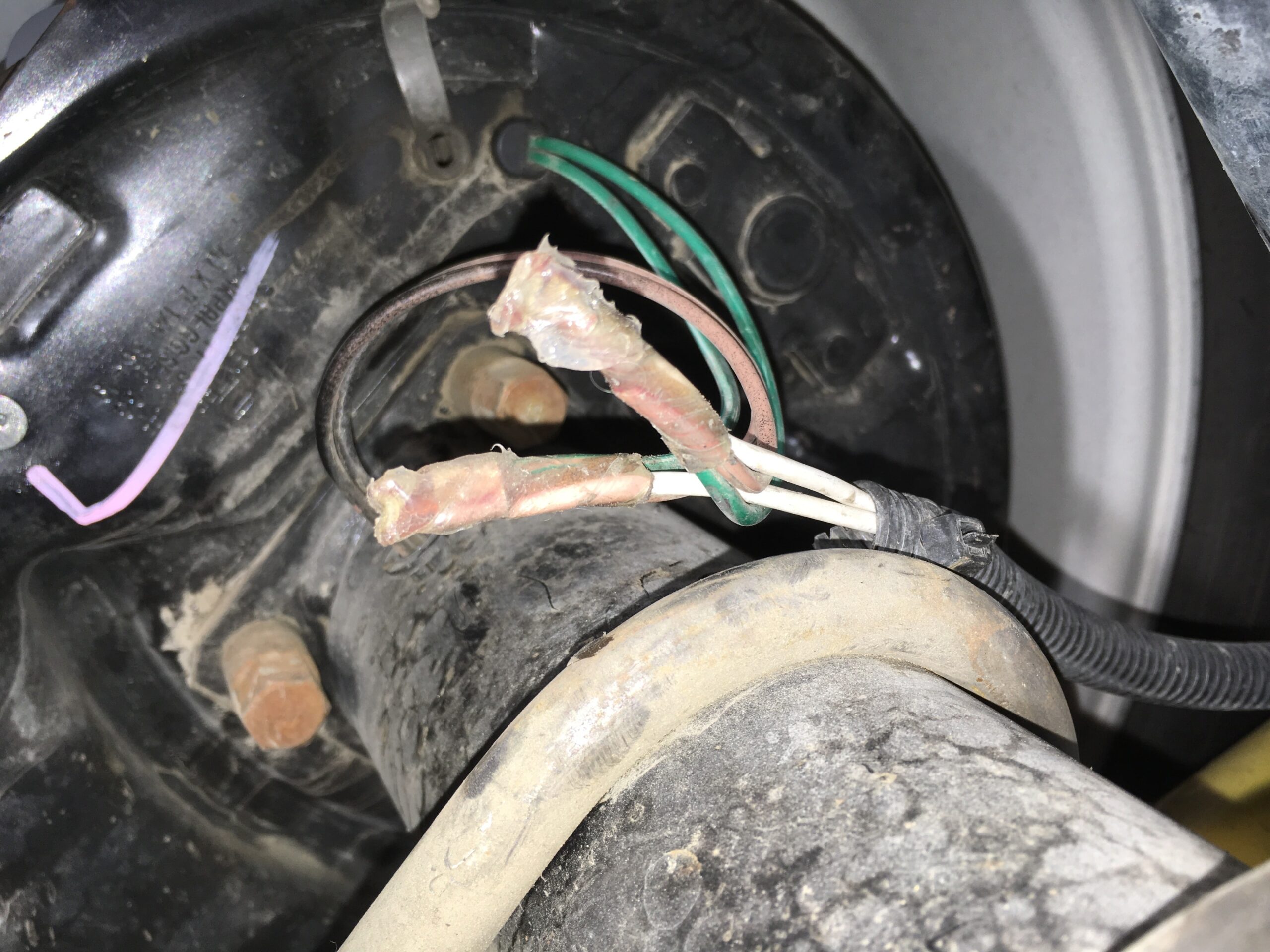
Electric brakes are a crucial component of any trailer, as they provide added safety and control when towing heavy loads. Proper wiring of the electric brakes is essential to ensure they function correctly. In this article, we will discuss the wiring diagram for electric brakes on a trailer.
Before we dive into the wiring diagram, it’s important to understand the basic components of an electric brake system. The system consists of a brake controller, battery, breakaway switch, wiring harness, and the electric brakes themselves. Each component plays a vital role in ensuring the brakes work effectively.
 Electric Brake Wiring Diagram Trailer
When it comes to wiring the electric brakes on a trailer, the key is to ensure a secure connection between each component. The wiring diagram will typically show the color-coding of the wires and the proper placement of each wire. It’s crucial to follow the diagram precisely to avoid any issues with the brakes not functioning correctly.
One common wiring diagram for electric brakes on a trailer involves connecting the brake controller to the vehicle’s battery and then running wiring from the controller to each brake assembly. The breakaway switch is also wired into the system to engage the brakes in the event of a trailer disconnect. Following the diagram step by step will ensure a proper and safe installation.
In addition to following the wiring diagram, it’s essential to regularly inspect and maintain the electric brake system on your trailer. Check for any loose connections, frayed wires, or signs of wear and tear. Keeping the system in good condition will help prevent any accidents or malfunctions while towing.
In conclusion, the wiring diagram for electric brakes on a trailer is a crucial guide to ensure proper installation and functionality of the brakes. By following the diagram carefully and maintaining the system regularly, you can ensure a safe and smooth towing experience. Remember to always prioritize safety when it comes to towing heavy loads with your trailer.