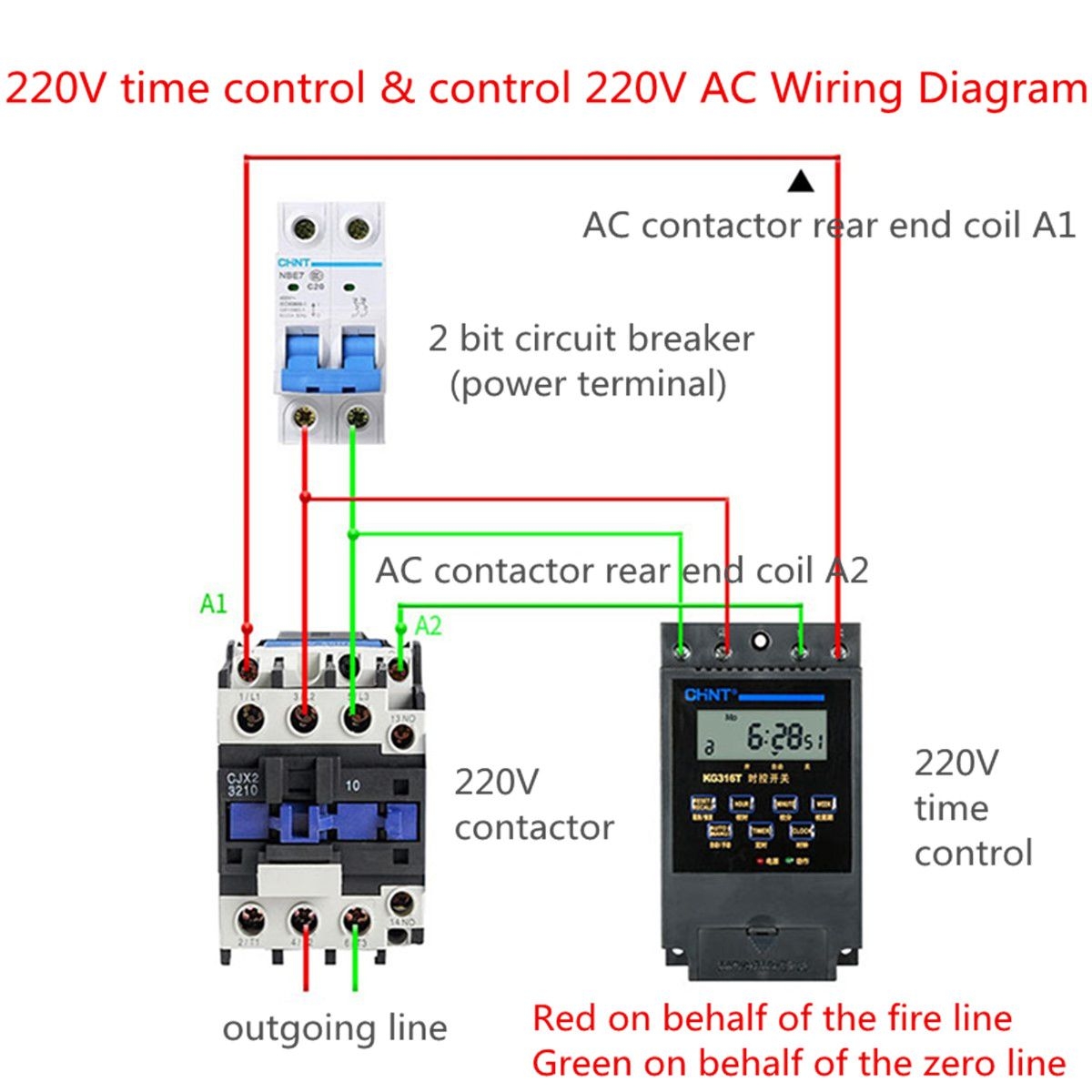
Contactor wiring diagrams are essential for understanding how to properly wire a contactor in an electrical system. A contactor is an electrical device that is used to control the flow of electricity in a circuit. It is commonly used in HVAC systems, lighting controls, and motor controls.
Understanding the wiring diagram of a contactor is crucial for ensuring that the contactor is wired correctly and functions properly. Incorrect wiring can lead to malfunctions, equipment damage, and even electrical hazards.
When looking at a contactor wiring diagram, it is important to pay attention to the terminal labels, wire colors, and connections. Each terminal on the contactor serves a specific purpose, such as power input, power output, control signal input, and ground.
Typically, a contactor wiring diagram will show how to connect the power supply, control signal, and load devices to the contactor. It will also indicate the correct wire sizes, wire colors, and terminal connections to use for each component.
It is recommended to follow the manufacturer’s instructions and guidelines when wiring a contactor. If you are not familiar with electrical wiring or unsure of how to wire a contactor, it is best to consult a professional electrician to ensure the job is done correctly and safely.
By understanding and following the wiring diagram for a contactor, you can ensure that your electrical system operates efficiently and safely. Proper wiring also helps prevent equipment damage and extends the lifespan of your contactor and other electrical components.
In conclusion, a contactor wiring diagram is a valuable tool for properly wiring a contactor in an electrical system. By following the diagram and guidelines provided by the manufacturer, you can ensure that your contactor functions correctly and safely. If you are unsure of how to wire a contactor, it is best to seek the help of a professional electrician to avoid any potential hazards.
