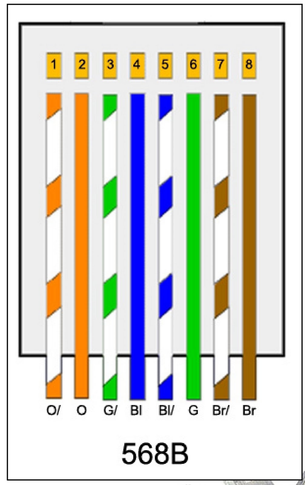
When it comes to setting up a network, understanding the different types of wiring diagrams is crucial. One popular choice is the Cat5b wiring diagram, which is commonly used for Ethernet connections. By following a Cat5b wiring diagram, you can ensure that your network is properly set up for optimal performance.
Before diving into the details of a Cat5b wiring diagram, it’s important to understand the basics of Cat5 cables. These cables are twisted pair cables that are typically used for Ethernet networks. The “b” in Cat5b stands for “balanced,” indicating that the wires are twisted in a way that helps reduce interference and crosstalk.
When following a Cat5b wiring diagram, you will typically see four pairs of wires: orange, green, blue, and brown. Each pair consists of a solid colored wire and a striped wire. These pairs are twisted together to help minimize signal degradation and interference.
To properly set up a Cat5b network, you will need to follow the wiring diagram carefully. This diagram will show you which wires to connect to each pin on a modular connector, such as an RJ45 connector. By following the diagram correctly, you can ensure that your network connections are reliable and efficient.
One key aspect of a Cat5b wiring diagram is the use of a crossover cable. In some cases, you may need to connect two devices directly to each other without using a switch or router. A crossover cable allows you to achieve this by crossing over the transmit and receive wires in the cable, enabling direct communication between the devices.
In conclusion, understanding and following a Cat5b wiring diagram is essential for setting up a reliable Ethernet network. By carefully connecting the wires according to the diagram, you can ensure that your network connections are stable and efficient. Whether you’re a professional network installer or a DIY enthusiast, knowing how to properly wire Cat5b cables can help you create a high-performing network for all your connectivity needs.
