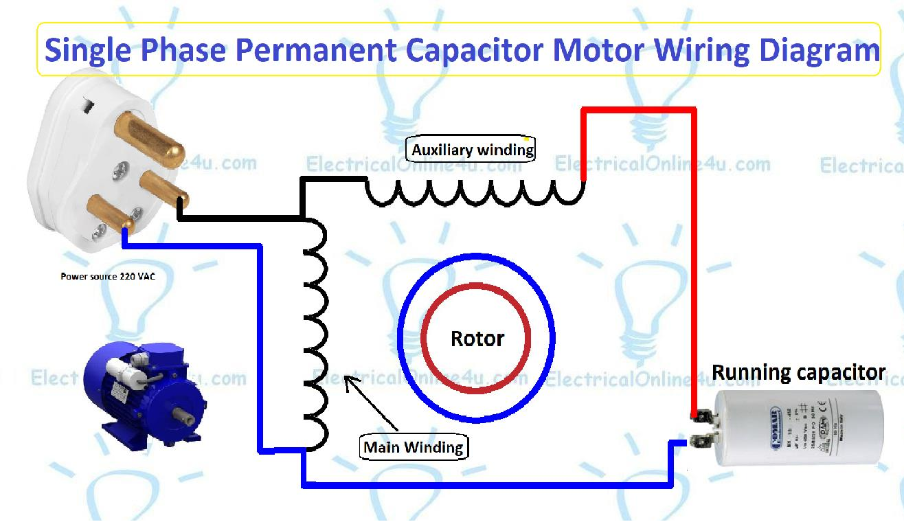
Capacitors are crucial components in electrical circuits, storing and releasing electrical energy as needed. Proper wiring of capacitors is essential to ensure the safety and efficiency of an electrical system.
Incorrect wiring of capacitors can lead to malfunctions, damage to equipment, and even electrical hazards. It is important to follow a capacitor wiring diagram to ensure that capacitors are connected correctly in a circuit.
Capacitor Wiring Diagram
Capacitors have two terminals – the positive terminal and the negative terminal. The wiring diagram will indicate which terminal should be connected to the positive and negative sides of the circuit. It is important to pay attention to the polarity of the capacitor to prevent damage.
In a typical capacitor wiring diagram, the positive terminal is usually denoted with a plus sign (+) and the negative terminal with a minus sign (-). It is important to connect the capacitor in the correct orientation to prevent reverse polarity, which can cause the capacitor to fail.
When wiring multiple capacitors in a circuit, it is important to connect them in parallel or series, depending on the desired outcome. Parallel wiring increases the total capacitance of the circuit, while series wiring decreases the total capacitance.
Following a capacitor wiring diagram ensures that capacitors are connected correctly in a circuit, preventing malfunctions and ensuring the safety and efficiency of the electrical system. Proper wiring also extends the lifespan of capacitors and other components in the circuit.
In conclusion, understanding and following a capacitor wiring diagram is crucial for the proper functioning of electrical circuits. By ensuring that capacitors are connected correctly and in the right orientation, you can prevent damage, malfunctions, and electrical hazards. Remember to always refer to a wiring diagram when working with capacitors to ensure the safety and efficiency of your electrical system.
