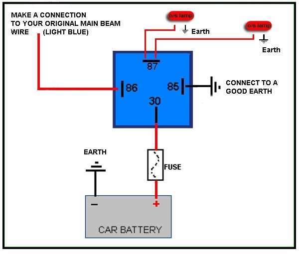
Relays are essential components in many electrical circuits, allowing a low power signal to control a high power circuit. A 4 pin relay is one of the most common types of relays used in automotive applications. Understanding how to wire a 4 pin relay is important for anyone working on their own vehicle electrical systems.
Relays typically have four pins: a coil pin, a common pin, a normally open (NO) pin, and a normally closed (NC) pin. The coil pin is used to activate the relay, while the common, NO, and NC pins are used to control the high power circuit. It is crucial to understand the wiring diagram of a 4 pin relay to ensure proper installation and functionality.
When wiring a 4 pin relay, it is important to identify the pins correctly. The coil pin is usually labeled as “85” or “86,” while the common pin is labeled as “30.” The NO and NC pins are labeled as “87” and “87a,” respectively. By following the wiring diagram, you can easily connect the relay to the power source and the high power circuit.
To wire a 4 pin relay, start by connecting the coil pin to the power source. The common pin should be connected to the power supply of the high power circuit, while the NO pin should be connected to the device that needs to be controlled. The NC pin can be left unconnected if not needed. Make sure to use appropriate wire gauges and connectors to ensure a secure connection.
After wiring the relay, it is important to test the circuit to ensure proper functionality. Apply power to the coil pin to activate the relay and check if the high power circuit is being controlled as expected. If the relay does not work correctly, double-check the wiring and connections to troubleshoot any issues.
In conclusion, understanding how to wire a 4 pin relay is essential for anyone working on automotive electrical systems. By following the wiring diagram and connecting the pins correctly, you can ensure proper installation and functionality of the relay. Always test the circuit after wiring to verify that everything is working correctly.
