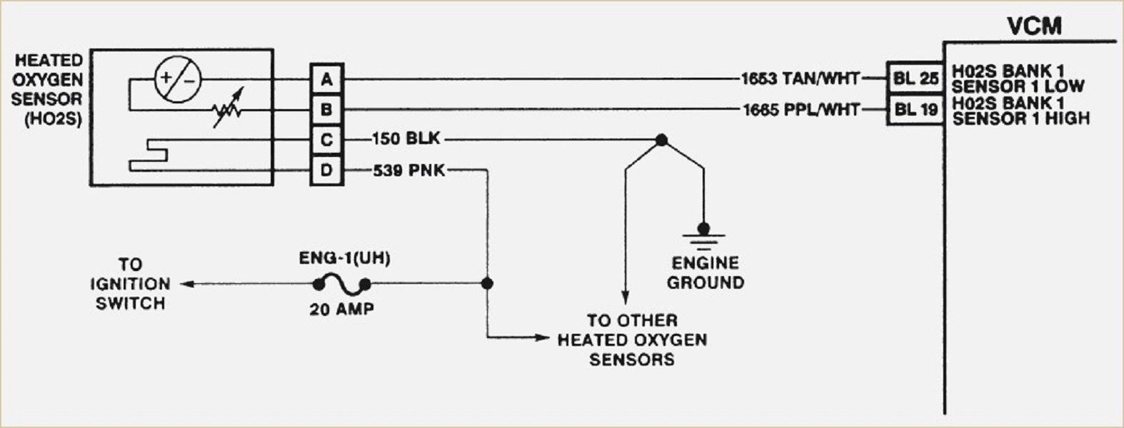
When it comes to installing a 4 wire oxygen sensor in your vehicle, it’s important to understand the wiring diagram to ensure proper connection and functionality. The oxygen sensor plays a crucial role in monitoring the air-fuel mixture in the engine and helps the vehicle run efficiently. By following the correct wiring diagram, you can ensure that the oxygen sensor is properly installed and functioning correctly.
Typically, a 4 wire oxygen sensor will have four wires – two for the heater circuit and two for the signal circuit. The heater circuit wires are usually colored black and gray, while the signal circuit wires are colored white and black. It’s important to connect these wires correctly to ensure that the sensor receives power and sends the correct signals to the engine control unit.
 4 Wire Oxygen Sensor Wiring Diagram
One common wiring diagram for a 4 wire oxygen sensor involves connecting the black wire to the vehicle’s ground, the gray wire to the sensor’s heater circuit, the white wire to the sensor’s signal circuit, and the black wire to the sensor’s signal ground. By following this diagram and making the appropriate connections, you can ensure that the oxygen sensor is properly installed and functioning correctly.
It’s important to note that the specific wiring diagram for a 4 wire oxygen sensor may vary depending on the make and model of your vehicle. It’s always a good idea to consult the vehicle’s service manual or a professional mechanic to ensure that you are following the correct wiring diagram for your specific vehicle. By taking the time to properly install the oxygen sensor, you can help ensure that your vehicle runs efficiently and effectively.
In conclusion, understanding the wiring diagram for a 4 wire oxygen sensor is essential for proper installation and functionality. By following the correct diagram and making the appropriate connections, you can ensure that the oxygen sensor is properly installed and sending the correct signals to the engine control unit. If you’re unsure about the wiring diagram for your specific vehicle, it’s always best to consult a professional to ensure that the oxygen sensor is installed correctly.