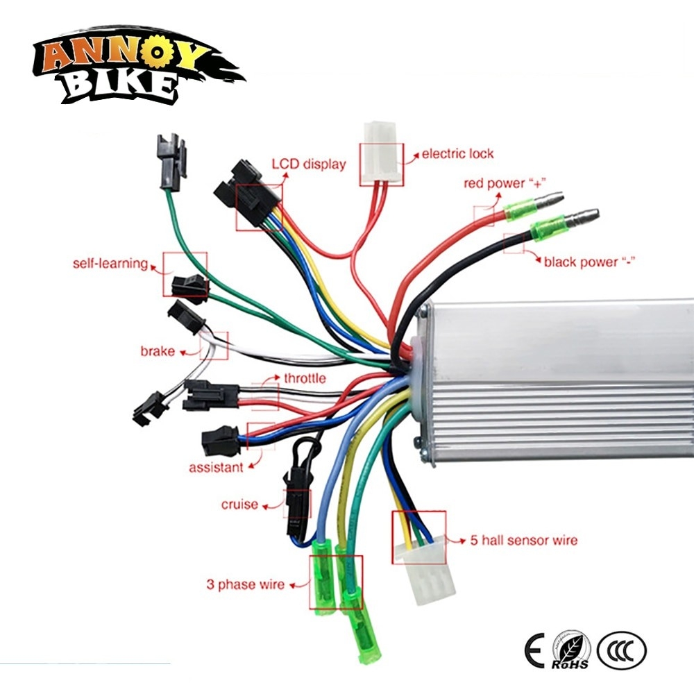
When it comes to setting up an electric bike, the controller wiring diagram is a crucial component to understand. The controller is responsible for regulating the flow of electricity from the battery to the motor, determining how fast and powerful the bike will be. With a 36-volt system, it’s important to follow the wiring diagram carefully to ensure proper functionality and safety.
Understanding the wiring diagram for a 36-volt e-bike controller is essential for anyone looking to customize or repair their electric bike. The diagram typically includes labels for the various wires and connections, indicating where each component should be attached. By following the diagram step by step, users can ensure that their e-bike operates smoothly and efficiently.
 36 Volt E Bike Controller Wiring Diagram
One key aspect of the wiring diagram is the color-coding of the wires. Different manufacturers may use different colors for their wires, so it’s important to refer to the specific diagram provided by the controller manufacturer. This will help users identify which wire corresponds to each component, such as the battery, motor, throttle, and brakes.
Another important consideration when working with a 36-volt e-bike controller wiring diagram is the placement of connectors and terminals. It’s crucial to make secure connections and avoid any loose or exposed wires that could lead to electrical shorts or malfunctions. Proper insulation and protection of the wiring will help prevent accidents and ensure the longevity of the e-bike system.
In conclusion, the 36-volt e-bike controller wiring diagram is a valuable resource for e-bike enthusiasts and technicians alike. By following the diagram carefully and paying attention to details such as wire colors and connection points, users can set up or troubleshoot their electric bike with confidence. Remember to prioritize safety and precision when working with the wiring diagram to enjoy a smooth and reliable e-bike riding experience.