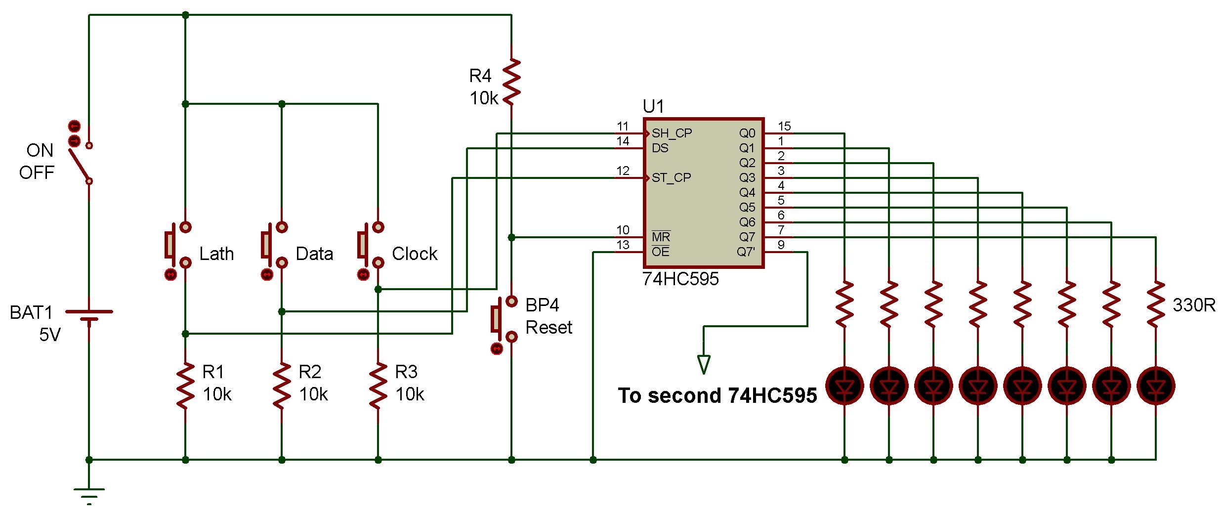
The 74hc595 is a popular shift register integrated circuit that is commonly used in electronics projects. It allows you to expand the number of output pins on your microcontroller by using serial communication. Understanding the wiring diagram for the 74hc595 is essential for successfully integrating it into your circuit.
Before diving into the wiring diagram, it is important to have a basic understanding of how the 74hc595 works. It has an 8-bit serial-in, parallel-out shift register that allows you to control multiple outputs using only three pins from your microcontroller – data, clock, and latch.
74hc595 Wiring Diagram
When wiring the 74hc595, you will typically connect the data pin to the MOSI pin of your microcontroller, the clock pin to the SCK pin, and the latch pin to a digital output pin. Additionally, you will need to connect the output pins of the 74hc595 to your desired components, such as LEDs or relays.
It is important to pay attention to the pinout of the 74hc595 to ensure that you are connecting the correct pins. The wiring diagram will show you how to properly connect the 74hc595 to your microcontroller and components, allowing you to effectively control multiple outputs with minimal pins.
Once you have wired the 74hc595 according to the diagram, you can start writing code to communicate with it. By sending data serially to the 74hc595, you can control the state of each output pin, allowing you to create complex lighting patterns or control multiple devices with ease.
In conclusion, understanding the wiring diagram for the 74hc595 is crucial for successfully incorporating it into your electronics projects. By following the correct wiring connections and utilizing the shift register capabilities of the 74hc595, you can expand the functionality of your microcontroller and create more complex projects.
