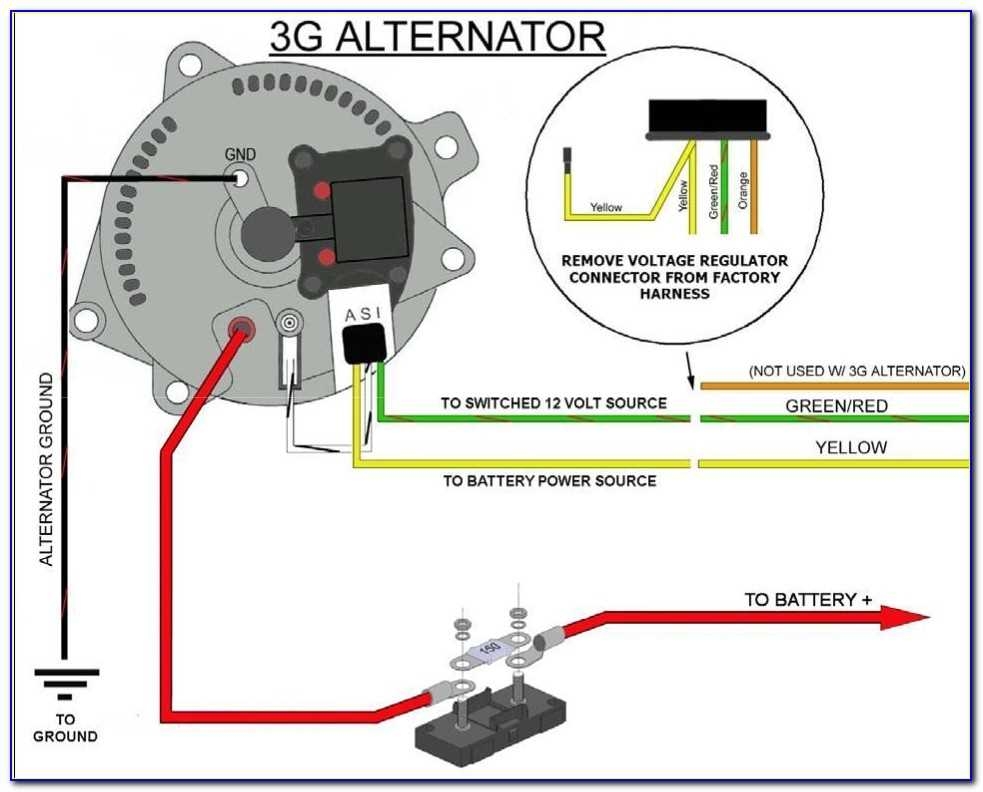
When it comes to automotive electrical systems, the alternator plays a crucial role in charging the battery and powering the electrical components of the vehicle. Understanding the wiring diagram of the alternator is essential for proper installation and troubleshooting.
The alternator wiring diagram is a schematic representation of the electrical connections between the alternator, battery, and other components in the vehicle’s electrical system. It provides a visual guide on how the wires should be connected to ensure proper functioning of the alternator.
Components of an Alternator Wiring Diagram
The alternator wiring diagram typically includes the following components:
- Alternator: This is the main component that generates electrical power to charge the battery.
- Battery: The battery stores the electrical energy generated by the alternator for use when the engine is not running.
- Starter: The starter motor is responsible for starting the engine by cranking it.
- Ignition switch: The ignition switch controls the flow of electrical power to the vehicle’s electrical system.
It is important to carefully follow the wiring diagram when installing or troubleshooting the alternator to avoid any electrical issues that could potentially damage the vehicle’s electrical system.
Additionally, understanding the alternator wiring diagram can help diagnose common electrical problems such as a dead battery, dimming headlights, or electrical malfunctions in the vehicle.
In conclusion, the alternator wiring diagram is a valuable tool for anyone working on the electrical system of a vehicle. By following the diagram accurately, you can ensure proper installation and troubleshooting of the alternator, ultimately leading to a well-functioning electrical system in your vehicle.
