When it comes to towing a trailer, having a brake controller is essential for safety. A trailer brake controller is a device that allows the driver to control the electric brakes on a trailer. Proper wiring is crucial for the controller to function correctly and ensure that the trailer brakes engage when needed.
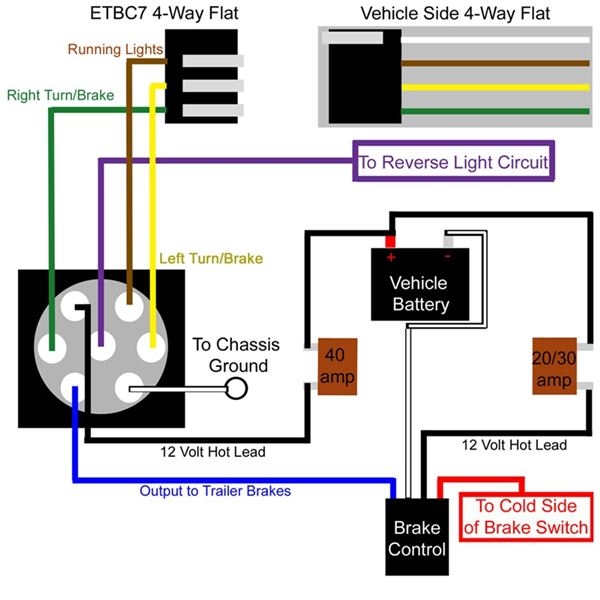
Understanding the wiring diagram for a trailer brake controller is important for installation and troubleshooting. The diagram typically shows the connections between the brake controller, the vehicle’s brake switch, the trailer brakes, and the power source. It is essential to follow the diagram carefully to ensure proper functionality.
 Trailer Brake Controller Wiring Diagram
One common wiring setup for a trailer brake controller includes connecting the controller to the vehicle’s brake switch, the trailer brakes, and the battery. The controller will receive a signal from the brake switch when the vehicle’s brakes are applied, sending power to the trailer brakes to help slow down the trailer. The battery provides the necessary power for the controller to operate.
It is crucial to use the correct gauge wire for the connections to ensure that the controller receives an adequate power supply. The wiring diagram will specify the appropriate wire gauge for each connection. Additionally, using quality connectors and securing the wiring properly will help prevent any issues with the controller’s function.
Testing the trailer brake controller after installation is also essential to ensure everything is working correctly. This can be done by connecting the trailer to the vehicle and applying the brakes to see if the trailer brakes engage. If the brakes do not engage, it may indicate a wiring issue that needs to be addressed.
In conclusion, understanding the wiring diagram for a trailer brake controller is crucial for proper installation and functionality. Following the diagram carefully, using the correct wire gauge, and testing the controller after installation are all important steps to ensure safe towing. By taking the time to wire the controller correctly, you can have peace of mind knowing that your trailer brakes will work effectively when needed.