5 pin rocker switches are commonly used in a variety of applications, from automotive to marine and industrial settings. These switches are versatile and easy to install, making them a popular choice for many different projects.
When it comes to wiring a 5 pin rocker switch, it’s important to follow the correct diagram to ensure proper functionality. By understanding the wiring diagram, you can easily install the switch and use it effectively for your specific needs.
 5 Pin Rocker Switch Wiring Diagram
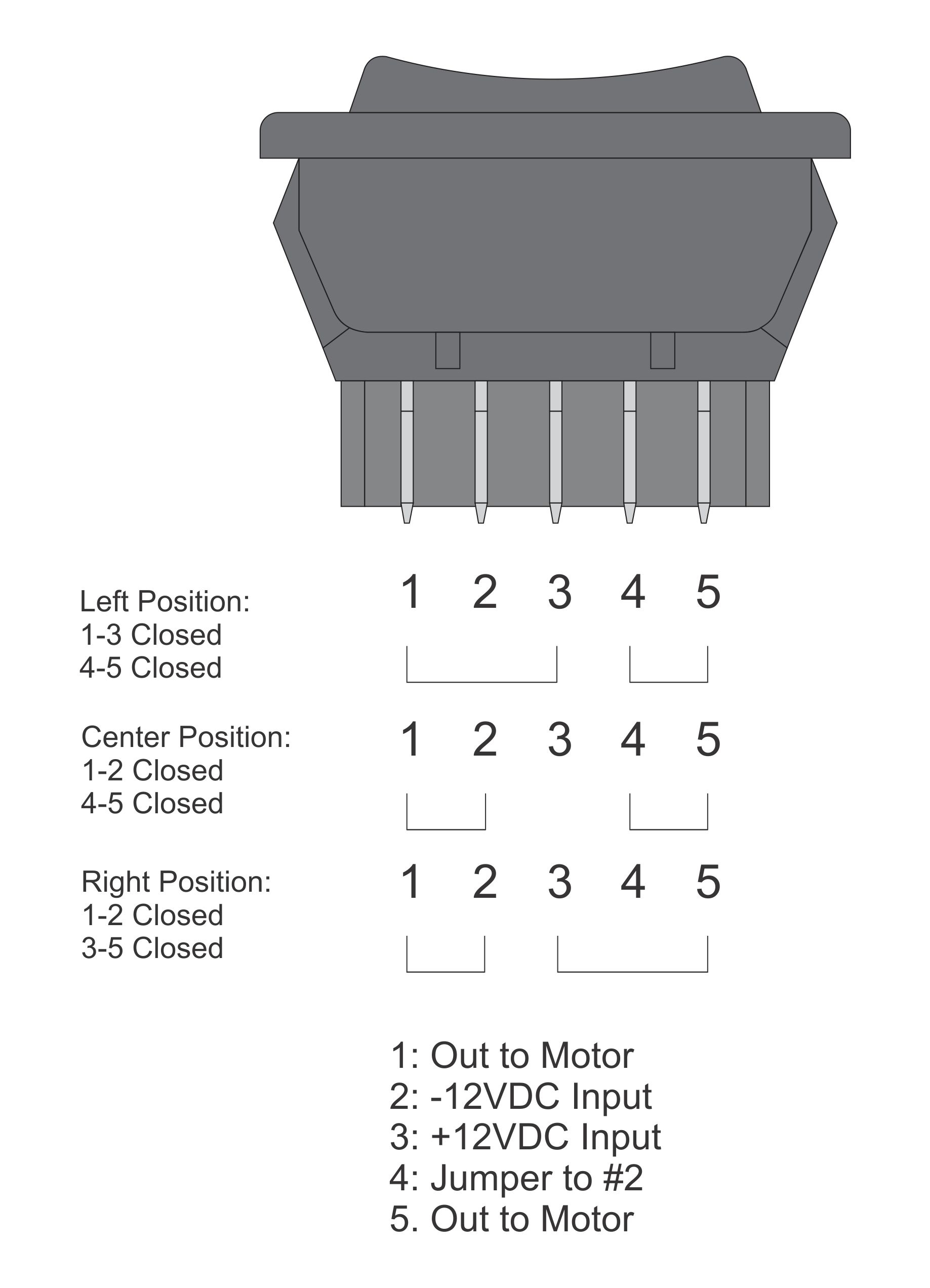
Here is a basic wiring diagram for a 5 pin rocker switch:
Pin 1 – Power input
Pin 2 – Power output
Pin 3 – Backlight (optional)
Pin 4 – Ground
Pin 5 – Power input
To wire the switch, connect the power input (Pin 1 and Pin 5) to the positive terminal of your power source. Connect the power output (Pin 2) to the device you want to control. Ground (Pin 4) should be connected to the negative terminal of your power source. If your switch has a backlight feature, connect Pin 3 to the positive terminal of your power source.
It’s important to double-check your wiring connections before powering up the switch to prevent any potential damage or malfunctions. Following the correct wiring diagram will ensure that your 5 pin rocker switch operates smoothly and efficiently.
With this simple wiring diagram, you can easily install a 5 pin rocker switch for your next project. Whether you’re working on a vehicle, boat, or industrial equipment, these switches are a reliable and convenient option for controlling various functions.
Overall, understanding the wiring diagram for a 5 pin rocker switch is essential for proper installation and operation. By following the correct wiring steps, you can confidently use the switch for your specific needs and projects.