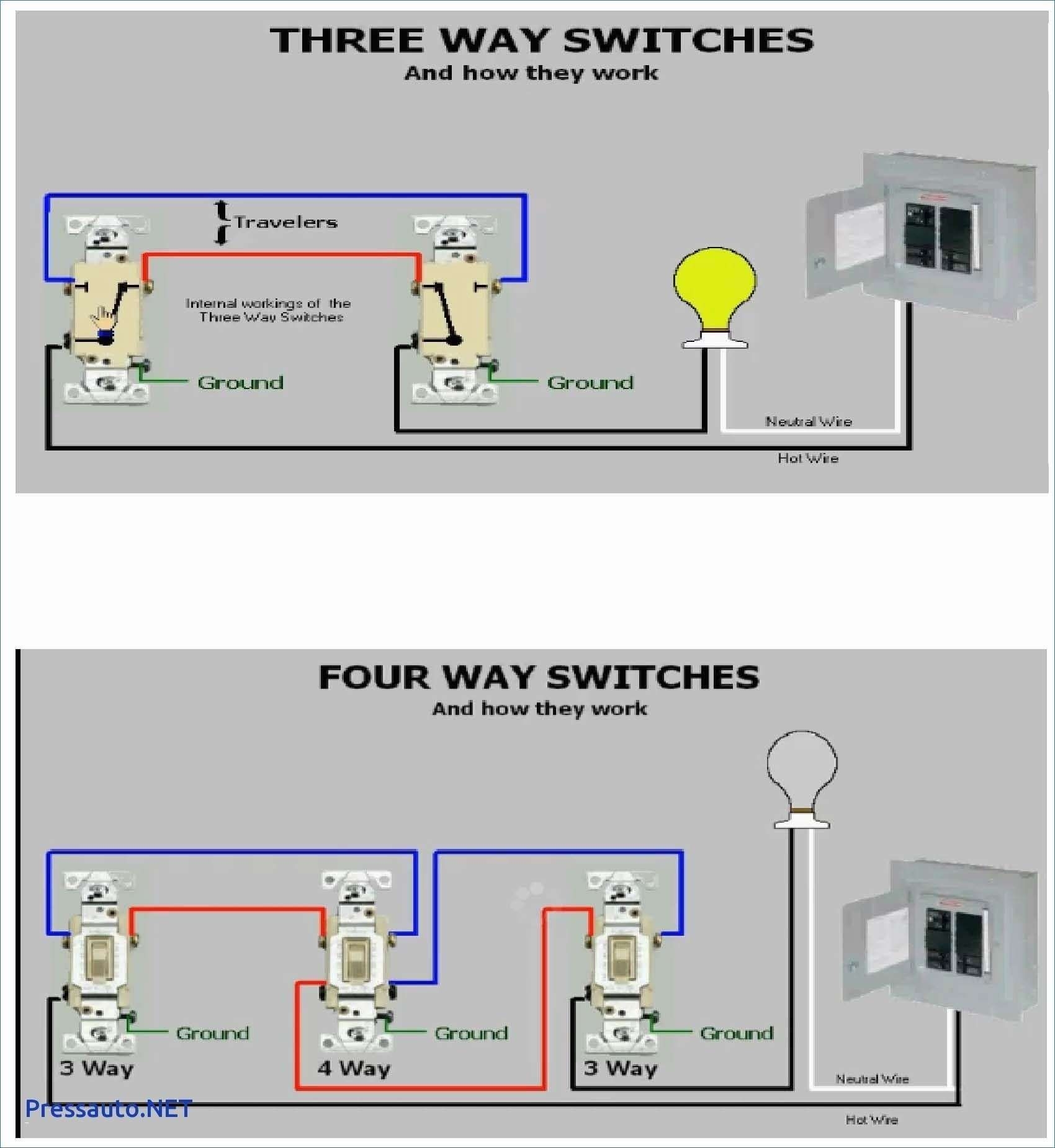
When it comes to wiring a 3 way switch, there are different ways to wire them depending on where the power source is located. One common scenario is having the power source at the switch, which means the power comes into one switch and then goes to the light fixture. This type of wiring diagram is often referred to as “power at switch.”
In a 3 way switch setup with power at the switch, you will have two switches and one light fixture. The switches are connected to each other with a traveler wire, allowing you to control the light from both switches. The power source is connected to one of the switches, and the other switch is connected to the light fixture.
 3 Way Switch Wiring Diagram Power At Switch
Here is a basic wiring diagram for a 3 way switch with power at the switch:

1. Start by turning off the power to the circuit at the breaker box.
2. Connect the power source (black wire) to the common terminal of the first switch.
3. Connect the traveler wires (usually red and black) to the traveler terminals of the first switch.
4. Connect the common terminal of the second switch to the light fixture (black wire).
5. Connect the traveler wires to the traveler terminals of the second switch.
6. Connect the white wires together with a wire nut and ground the switches and light fixture.
Make sure to test the circuit before turning the power back on to ensure everything is wired correctly. If you are unsure about any part of the wiring process, it is always best to consult a professional electrician.
Overall, wiring a 3 way switch with power at the switch can be a bit more complicated than other setups, but with the right diagram and careful planning, you can successfully wire the switches and light fixture to work together seamlessly.