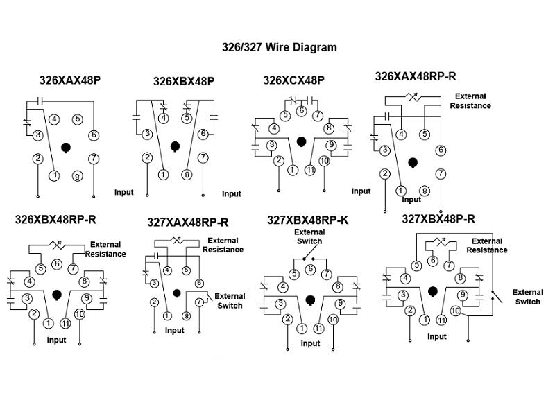
Relays are essential components in electrical circuits that help control high voltage circuits with low voltage signals. One common type of relay is the 8 pin relay, which is widely used in various applications. Understanding the wiring diagram of an 8 pin relay is crucial for ensuring proper installation and operation.
By following the wiring diagram, you can easily connect the relay to the power source, load, and control signals. This will help prevent any potential wiring errors that could lead to malfunction or damage to the relay and other components in the circuit.
8 Pin Relay Wiring Diagram
Typically, an 8 pin relay will have the following pin configuration:
- Pin 1: Coil A
- Pin 2: Coil A
- Pin 3: Common
- Pin 4: Normally Open (NO)
- Pin 5: Normally Closed (NC)
- Pin 6: Normally Open (NO)
- Pin 7: Normally Closed (NC)
- Pin 8: Common
When wiring an 8 pin relay, it is important to correctly connect the coil terminals to the power source and control signals. The common, normally open, and normally closed terminals are used to connect the relay to the load and control the flow of current through the circuit.
It is recommended to refer to the manufacturer’s datasheet or wiring diagram for specific instructions on how to wire the 8 pin relay for your particular application. This will ensure that the relay is connected correctly and will function as intended.
Overall, understanding the wiring diagram of an 8 pin relay is essential for proper installation and operation in electrical circuits. By following the correct wiring procedures, you can ensure the reliability and safety of your circuit while maximizing the performance of the relay.
Take the time to study and understand the wiring diagram of the 8 pin relay before proceeding with the installation. This will help you avoid costly mistakes and ensure the successful operation of your electrical circuit.
