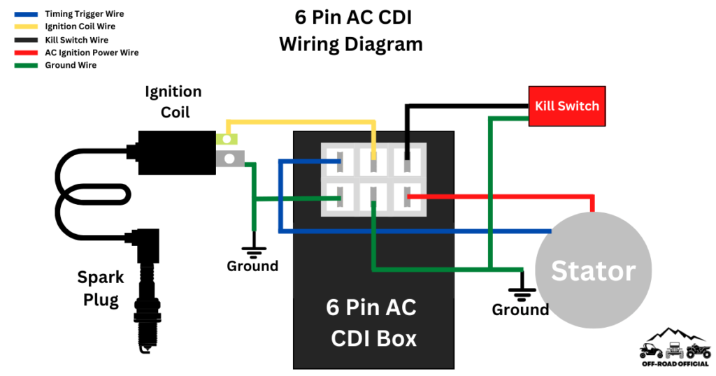
When it comes to wiring diagrams for CDI units, the 6 Pin CDI Wiring Diagram is a popular choice among many enthusiasts and mechanics. Understanding how to properly wire a CDI unit is essential for ensuring the smooth operation of your vehicle or equipment.
Whether you are working on a motorcycle, ATV, or any other vehicle that requires a CDI unit, having a clear understanding of the wiring diagram is crucial. This will help you troubleshoot any issues that may arise and ensure that everything is connected correctly.
Typically, a 6 Pin CDI unit will have wires for power, ground, ignition coil, pulse generator, and kill switch. Each wire serves a specific function and must be connected properly to ensure that the CDI unit functions correctly. It is important to refer to the wiring diagram provided by the manufacturer to ensure proper connections.
One common mistake when wiring a CDI unit is mixing up the wires or connecting them incorrectly. This can lead to issues such as no spark, erratic engine behavior, or even damage to the CDI unit itself. Taking the time to carefully follow the wiring diagram and double-checking your connections can save you a lot of time and headaches in the long run.
In conclusion, understanding the 6 Pin CDI Wiring Diagram is essential for anyone working with CDI units. By following the wiring diagram provided by the manufacturer and making sure all connections are correct, you can ensure the smooth operation of your vehicle or equipment. Remember to take your time, double-check your work, and seek help if needed to avoid any potential issues.
