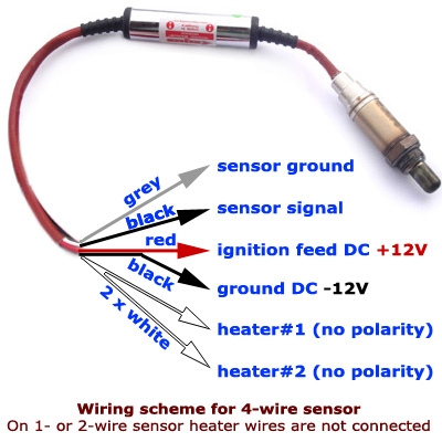
When it comes to installing a 4 wire lambda sensor, it is important to understand the wiring diagram to ensure proper functionality. The lambda sensor plays a crucial role in monitoring the air-fuel ratio in the engine and helps the vehicle’s computer adjust the fuel mixture for optimal performance.
Before diving into the wiring diagram, it is essential to identify the four wires of the lambda sensor. These wires typically include a signal wire, a ground wire, and two heater wires. The signal wire is responsible for transmitting the oxygen content information to the engine control unit (ECU), while the heater wires help regulate the sensor’s temperature for accurate readings.
 4 Wire Lambda Sensor Wiring Diagram
When wiring the lambda sensor, it is crucial to connect the correct wires to the corresponding terminals. The signal wire should be connected to the ECU’s input terminal, while the ground wire should be securely grounded to the vehicle’s chassis. The two heater wires must be connected to a power source to ensure the sensor reaches its operating temperature quickly.
It is recommended to refer to the vehicle’s service manual or consult with a professional mechanic to obtain the specific wiring diagram for the 4 wire lambda sensor. Following the diagram accurately will prevent any wiring errors that could lead to sensor malfunctions and potential damage to the engine.
Once the wiring is completed, it is essential to test the lambda sensor to ensure it is functioning correctly. This can be done by using a multimeter to measure the sensor’s output voltage and comparing it to the manufacturer’s specifications. Any deviations from the expected values may indicate a wiring issue that needs to be addressed promptly.
In conclusion, understanding the 4 wire lambda sensor wiring diagram is crucial for proper installation and functionality. By following the diagram accurately and testing the sensor after installation, you can ensure that your vehicle’s engine runs smoothly and efficiently. Remember to seek professional assistance if needed to avoid any potential wiring errors.