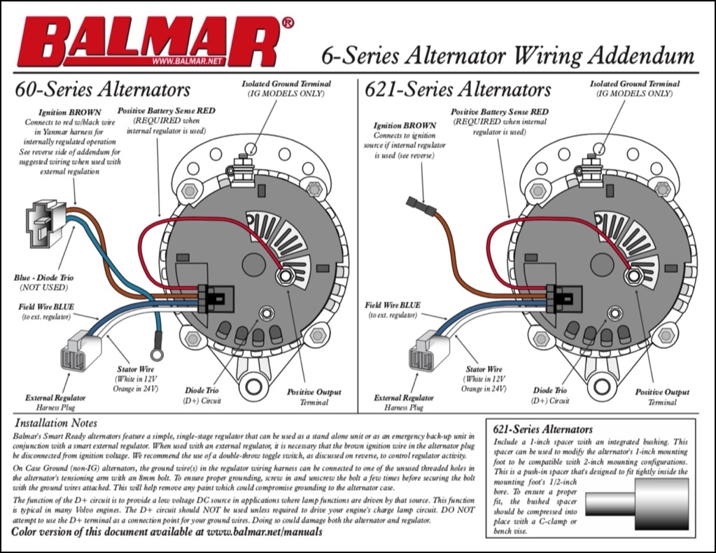
When it comes to upgrading or replacing the alternator in your vehicle, it’s important to have a clear understanding of the wiring diagram. The 4 wire alternator wiring diagram is a popular choice for many car enthusiasts as it provides a simple and efficient way to connect the alternator to the battery and electrical system.
With a 4 wire alternator wiring diagram, you’ll typically have two main power wires, a ground wire, and a sensing wire. The two power wires are responsible for carrying the current from the alternator to the battery, while the ground wire provides a return path for the current. The sensing wire is used to monitor the voltage output of the alternator and regulate the charging system accordingly.
 4 Wire Alternator Wiring Diagram
One of the key benefits of using a 4 wire alternator wiring diagram is that it allows for a more precise control of the charging system. By monitoring the voltage output of the alternator, the sensing wire can help prevent overcharging or undercharging of the battery, which can extend the life of the battery and improve overall performance.
Another advantage of the 4 wire alternator wiring diagram is that it simplifies the installation process. With clear labeling of the power, ground, and sensing wires, even beginners can easily connect the alternator to the battery and electrical system without any confusion. This can save time and effort, especially for those who are new to working on their vehicles.
In conclusion, the 4 wire alternator wiring diagram is a reliable and efficient option for connecting the alternator to the battery and electrical system in your vehicle. With its clear layout and precise control of the charging system, it’s a popular choice among car enthusiasts looking to upgrade or replace their alternator. By following the wiring diagram carefully, you can ensure a smooth and successful installation process that will help improve the performance and longevity of your vehicle’s electrical system.