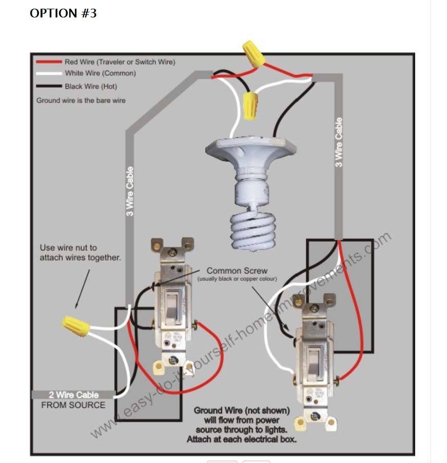
When it comes to installing a 3-way switch in your home, having the right wiring diagram is essential. A 3-way switch allows you to control a light or group of lights from two different locations. This can be useful in areas such as stairwells, hallways, or large rooms where multiple switches are needed.
Understanding the wiring diagram for a 3-way switch is crucial to ensure that the switch functions properly. The diagram will show you how to wire the switches, the power source, and the light fixture in a way that allows for seamless operation from both locations.
 3-Way Switch Wiring Diagram Pdf
One common method is the “circuit loop” design, where power is fed through the light fixture and then routed to the switches. This type of wiring requires a hot wire, a neutral wire, and a traveler wire between the two switches. By following the diagram carefully, you can easily set up this configuration in your home.
Another important aspect of the wiring diagram is identifying the common terminal on each switch. This terminal is typically a darker color and is connected to the power source. The traveler wires will be connected to the other terminals on the switches, allowing for communication between the two switches.
Once you have the wiring in place according to the diagram, you can test the switches to ensure they are working correctly. If the switches are not functioning as expected, double-check the wiring connections and make any necessary adjustments. With the right diagram and a little patience, you can successfully install a 3-way switch in your home.
In conclusion, having a reliable wiring diagram is essential when installing a 3-way switch in your home. By following the diagram carefully and understanding the different components of the wiring setup, you can easily set up the switch for seamless operation. Whether you’re a DIY enthusiast or a professional electrician, having the right information at your fingertips is key to a successful installation.