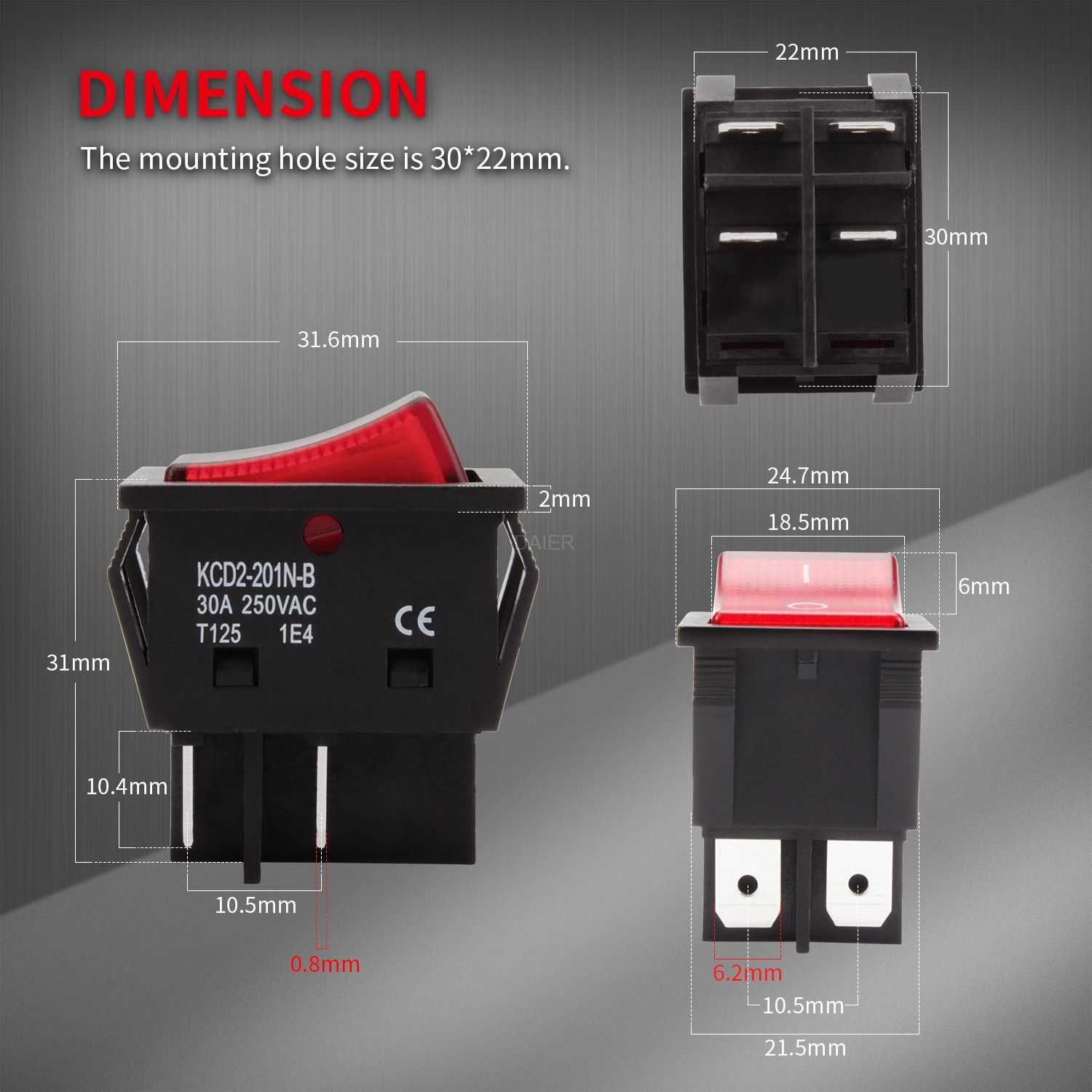
When it comes to wiring a 3 pin illuminated rocker switch, it’s important to follow the correct diagram to ensure proper functionality. These switches are commonly used in automotive, marine, and industrial applications to control various devices.
Understanding how to wire a 3 pin illuminated rocker switch can be essential for anyone looking to add or replace one in their setup. By following the correct wiring diagram, you can easily install the switch and have it working in no time.
 3 Pin Illuminated Rocker Switch Wiring Diagram
Here is a simple wiring diagram for a 3 pin illuminated rocker switch:
Pin 1: Connect to the power source, typically the positive terminal of the battery.
Pin 2: Connect to the accessory or device you want to control with the switch.
Pin 3: Connect to the ground or negative terminal of the battery.
It’s important to note that the illuminated rocker switch will have an additional terminal for the LED light. This terminal will also need to be connected to power for the light to function properly.
Once you have connected all the terminals according to the wiring diagram, you can test the switch to ensure it is working correctly. When the switch is in the “on” position, the LED light should illuminate, indicating that the circuit is closed and the device is powered.
Overall, wiring a 3 pin illuminated rocker switch is a simple process as long as you follow the correct diagram. With the right connections in place, you can easily control various devices with the flip of a switch.
So, whether you’re looking to upgrade your vehicle’s lighting or add a new control switch to your boat, knowing how to wire a 3 pin illuminated rocker switch can come in handy. With this diagram as a guide, you’ll be able to complete the installation with ease.