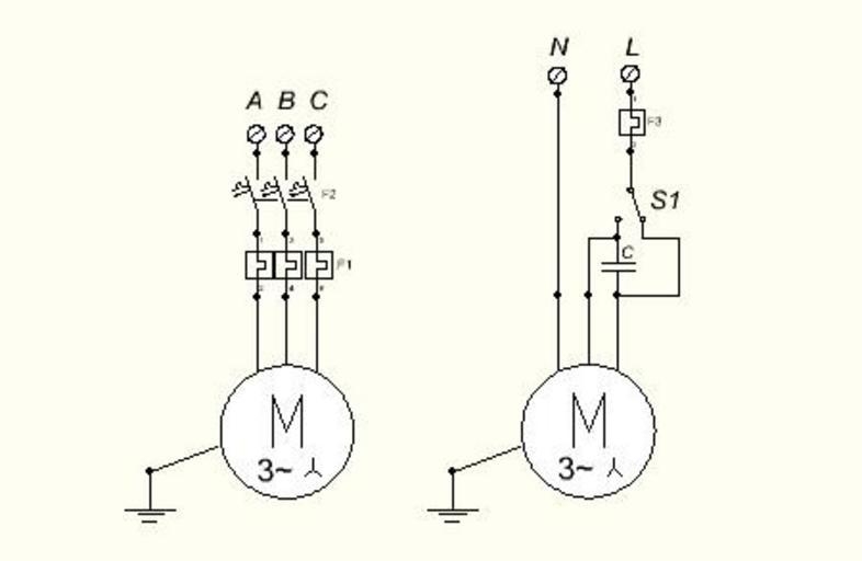
When it comes to wiring a three-phase motor, it is essential to follow the correct diagram to ensure proper functionality and safety. Understanding the wiring diagram is crucial for anyone looking to install or troubleshoot a three-phase motor system.
Three-phase motors are commonly used in industrial applications due to their efficiency and power output. By following the wiring diagram correctly, you can ensure that the motor operates smoothly and efficiently.
Wiring Diagram
The wiring diagram for a three-phase motor typically consists of three sets of wires – one for each phase. Each wire must be connected to the corresponding terminal on the motor to ensure that it receives the correct voltage and current.
It is important to note that the wiring diagram may vary depending on the specific model and manufacturer of the motor. Always refer to the manufacturer’s instructions and guidelines when wiring a three-phase motor to avoid any potential issues.
When wiring a three-phase motor, it is essential to pay attention to the color coding of the wires. Typically, the wires are color-coded to indicate their phase – red for phase A, yellow for phase B, and blue for phase C. By following the color-coding scheme, you can easily identify and connect the wires correctly.
In addition to the color-coding, the wiring diagram also includes information on how to connect the motor to the power supply and any additional components, such as a starter or overload relay. Following the diagram step by step will ensure that the motor is wired correctly and functions as intended.
In conclusion, understanding the wiring diagram for a three-phase motor is essential for proper installation and operation. By following the diagram provided by the manufacturer and paying attention to color-coding and connections, you can ensure that the motor operates smoothly and efficiently. If you are unsure about any aspect of the wiring process, it is always best to consult a professional electrician for assistance.
